At Extrusion & Axis, purchases made through some links may earn us an affiliate commission at no extra cost to you. How Extrusion & Axis affiliate funding works
A quick release (QR) adapter serves as the mechanical bridge between a steering column or direct drive wheelbase and the steering wheel rim. While originally engineered for motorsport cockpits to facilitate rapid driver egress, quick releases are now standard equipment across both automotive tuning and high-torque sim racing rigs. However, mechanical mismatch remains a common pitfall: mismatched pitch circle diameters (PCD), incompatible wheelbase shaft splines, and excessive stack height can compromise driving ergonomics or introduce mechanical slop.
Choosing the correct quick release requires auditing three specific dimensions: the wheelbase-side shaft interface, the rim-side bolt pattern, and the assembly's overall axial depth.
The majority of motorsport and sim racing rims employ a 6-hole pattern arranged on a 70 mm Pitch Circle Diameter (standardized by MOMO, Sparco, and OMP) or a 74/75 mm PCD (common to Nardi and Personal patterns). Verify your rim's bolt-circle spacing before selecting an adapter flange.
Direct Drive Sim Rig vs. Universal Automotive Flanges
In sim racing, quick releases must endure rapid high-frequency directional reversals without developing rotational backlash or axial play. Direct drive ecosystems frequently utilize a ball-bearing detent quick release design derived from automotive D1-SPEC or NRG geometries, adapted to proprietary or semi-standardized shaft stubs.
If you operate direct drive wheelbases from brands such as Simagic or MOZA, your base shaft features a specific ball-locking male collar. A compatible QR must seat securely over these detent bearings and align mechanically with the wheelbase shaft diameter.

The MUGE QR040 Hub Adapter listed above is engineered around the 6-hole 70 mm PCD pattern and explicitly targets direct drive platforms like the MOZA and Simagic ecosystems (such as the M10 or Alpha series). A key mechanical consideration for sim rigs is electrical data transmission: while wireless wheel connection or coiled USB cables are common, the QR's internal hollow bore determines whether internal wiring harnesses, grounding contacts, or quick-connect PCB headers can pass through without binding during rotation.
Universal Dual-PCD Hubs for Column Boss Kits
In real-world vehicle installations, quick release hubs generally do not attach directly to a bare steering shaft. Instead, they bolt onto an intermediate, vehicle-specific splined boss kit. The universal automotive quick release then fastens between that boss kit and your aftermarket steering wheel.
These units often incorporate a dual-drilled flange featuring alternating threaded holes to accommodate both common 6-bolt standards simultaneously.
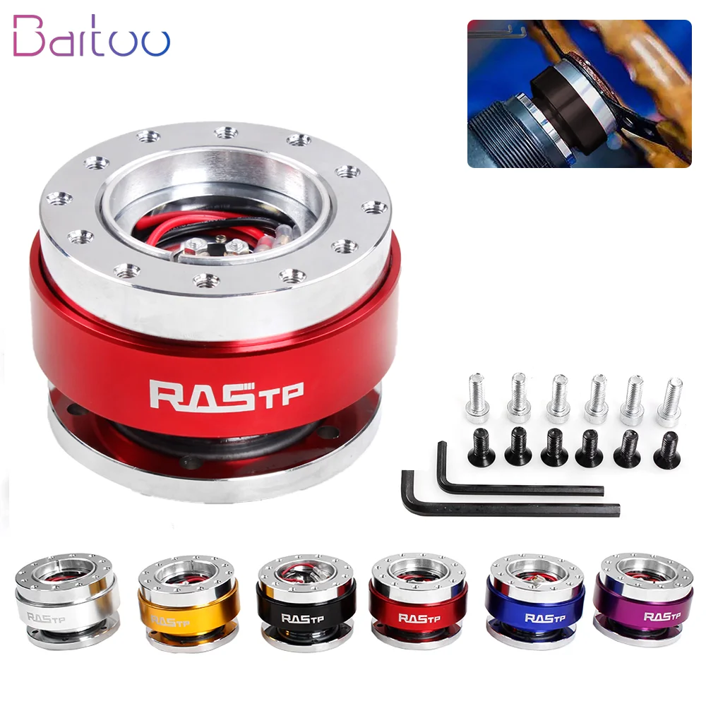
The Bartoo QR030 Hub Adapter provides mounting provisions for both 70 mm and 75 mm PCD configurations. Universal tuning units of this type typically utilize a spring-loaded outer locking sleeve over an internal splined or ball-locked core. These automotive models often include brass horn contact plates and internal jumper wires in the center bore. When applying universal tuning hubs to custom sim rig adapters, note that the internal contact plates can be unbolted or bypassed if routing non-automotive wiring.
Stack Height and Axial Cockpit Packaging
Every quick release adds axial length to the steering column. Adding a standard-depth adapter (typically between 50 mm and 70 mm) shifts the steering rim closer to the driver's chest. In an automobile, this can push the rim uncomfortably close to the driver and move turn-signal stalks out of natural finger reach. In an aluminum profile sim cockpit, extended stack height increases the lever-arm load on the wheelbase front shaft bearing and alters the elbow angle.
When physical packaging space is tight or the existing boss kit already provides substantial offset, a low-profile thin adapter provides the necessary quick-detach functionality while minimizing reach displacement.

The Dynoracing Thin Version Hub Adapter employs a low-profile mechanism with a push-pin safety release rather than a deep sliding sleeve collar. While a thin form factor saves valuable axial depth, keep two trade-offs in mind:
- Reduced internal clearance: Low-profile designs leave minimal interior volume for housing connector pins, coiled USB breakout cables, or bulky horn connectors.
- Flange thread depth: Thin plates offer fewer engaged threads for the mounting hardware, requiring exact bolt-length matching to prevent bottoming out against the hub face.
Technical Specification Comparison
| Model Reference | Primary PCD Support | Release Mechanism | Target Application |
|---|---|---|---|
| MUGE QR040 | 70 mm (6-Hole) | Ball-detent spring collar | Direct drive sim rigs (MOZA, Simagic, etc.) |
| Universal QR030 | Dual 70 mm / 75 mm (6-Hole) | Sleeve-lock snap-off | Vehicle boss kits, universal 6-bolt rims |
| Dynoracing Thin Version | Standard 6-Hole | Push-button pin release | Cockpits prioritizing minimal stack depth |
Verification Checklist Before Purchase
To avoid fitment failure and mechanical play, run through the following checks prior to ordering:
- Measure Your Rim’s PCD: Measure center-to-center across opposite bolt holes on your 6-bolt steering wheel. If it measures 70 mm (~2.75 in), it follows the MOMO/OMP standard. If it measures ~74 mm (~2.9 in), confirm the hub has a dual-drilled 74/75 mm flange.
- Determine Base Shaft Compatibility: Sim racing wheelbases with integrated quick release shafts (like Simagic or MOZA) mate directly to standard 4-ball or 6-ball QR female housings. Automotive columns require an underlying vehicle-specific splined boss kit to receive the male side of the QR.
- Account for Fastener Threading: Check whether the QR flange holes are countersunk through-holes or pre-threaded M5/M6 taps. Fasteners must thread cleanly into their mating surface without bottoming against internal mechanism housings.
